

Rotation matrices are embedded in everyday life, even if we hardly notice their presence. How does our phone know what is “up” or “down”? How does a car understand if it is going uphill or downhill? How does a spacecraft know where to point its antennas to transfer its precious data? Rotation matrices are an essential tool when the attitude of an object is needed.
There are two interpretations that can be assigned to a rotation matrix, depending on the context or by convention:
- A matrix that rotates a reference frame with respect to another one
- A matrix that rotates a vector in a given reference frame
In this post both concepts are explored leveraging mathematical notation and examples.
Where do rotation matrices come from?
Let’s start from the basic function of a rotation matrix, which must be able to rotate a vector without changing its length. That is, the norm of a given vector u must stay the same before and after the multiplication with the rotation matrix R as
|| R u || = || u ||
Equivalently, it is possible to write that
(R u)^T (R u) = u^T u
or
u^T R^T R u = u^T u
Which holds when R^T R = I or R^T = R^{-1}. This is the condition for orthogonality, which imposes that the rows and columns of R must be orthogonal and unit vectors. Moreover, the determinant can only be det(R) = \pm 1 to retain the original vector length. When the determinant is negative, an improper rotation or rotoreflection is obtained, which is a rotation combined with a symmetry operation, while rotation only occurs when the determinant is positive.
What is the expression of a rotation matrix?
Consider two bases belonging to different reference frames, collected as
F_b = [b_x, b_y, b_z] ^T
F_a = [a_x, a_y, a_z] ^T
The relationship between them, which is how one frame can be expressed using the other one, can be obtained through a linear combination as
\left[\begin{array}{c}b_x\\b_y\\b_z\end{array}\right] = \left[\begin{array}{ccc}C_{xx}&C_{xy}&C_{xz}\\ C_{yx}&C_{yy}&C_{yz}\\ C_{zx}&C_{zy}&C_{zz}\end{array}\right]\left[\begin{array}{c}a_x\\ a_y\\ a_z\end{array}\right]
or
F_b = C_{ba} F_a
where the matrix C_{ba} is the 3×3 rotation matrix that describes the attitude of reference frame B with respect to reference frame A . In other words, it contains the components of versors of reference frame B expressed in frame A by row. This is the first interpretation of a rotation matrix: it stores the information of the relative attitude between two given reference frames and as such can rotate one reference frame into the other one.
Matrix C_{ba} takes a simple form when it represents a rotation around one of the three main axis x, y or z . These rotations are often referred to as principal rotations and yield the following expressions
C_x = C_1 = \left[\begin{array}{ccc} 1& 0 & 0\\ 0& \cos(\theta_x)&\sin(\theta_x)\\ 0& -\sin(\theta_x) & \cos(\theta_x)\end{array}\right]
C_y = C_2 = \left[\begin{array}{ccc} \cos(\theta_y)& 0 &-\sin(\theta_y)\\0&1&0\\ \sin(\theta_y) & 0 &\cos(\theta_y)\end{array}\right]
C_z = C_3 = \left[\begin{array}{ccc} \cos(\theta_z)&\sin(\theta_z)&0\\ -\sin(\theta_z) & \cos(\theta_z)&0 \\ 0& 0 & 1 \end{array}\right]
Rotating a vector in a reference frame
Since a rotation matrix maps versors of a given reference frame B onto reference frame A, it is trivial to rotate a vector u between the two frames. Call this vector u_a when written in a frame and u_b when in b frame; It is possible to describe the relation between u_a and u_b using the same equation as before
u_b = C_{ba}u_a
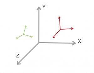
Suppose now to rotate a vector inside a given reference frame A, so that only one reference frame is involved. By noticing that a rotation of a reference frame by an angle \theta is equivalent to a rotation of a vector by an angle -\theta (for what concerns the relative vector/frame attitude), as shown in Fig. [2], the expression
u_b = u_a’ = C_{ba} u_a
can be interpreted also as a rotation of a vector inside reference frame A by an angle -\theta. Indeed u_a’ is equal to u_a vector rotated by a negative angle -\theta. In order to be consistent with the sign of the rotation angle, the rotation matrix can be inverted to obtain a positive vector rotation \theta relative to reference frame A. The expression then becomes
u_a’ = C_{ba}^T u_a = C_{ab} u_a

A simple example
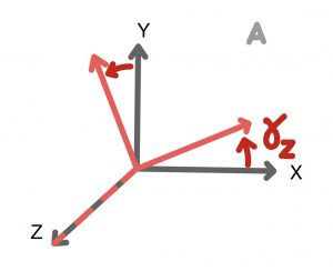
Consider the reference frame A and rotate it by 30 degrees around the z axis, as shown in Fig. [3].
The expression for the rotation matrix C_{ba} is
C_{ba} = \left[\begin{array}{ccc}0.86& 0.50& 0\\-0.50& 0.86& 0\\0& 0& 1\end{array}\right]
Since F_b = C_{ba} F_a, frame B (Fig. [3] in red) expressed in frame A becomes
F_b= \left[\begin{array}{ccc}0.86& 0.50& 0\\-0.50& 0.86& 0\\0& 0& 1\end{array}\right]\left[\begin{array}{c}a_{x}\\ a_{y}\\ a_{z}\end{array}\right] = \left[\begin{array}{c}0.86 a_{x} +0.50 a_{y}+0 a_{z}\\ -0.50 a_{x}+0.86 a_{y}+0 u_{az}\\ 0 a_{x} +0 a_{y}+ 1 a_{z}\end{array}\right]
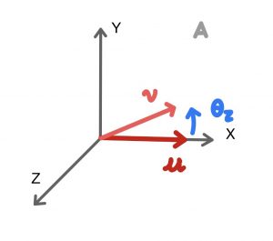
Consider now a vector u = (1,0,0)^T in A frame and rotate it by 30 degrees: multiply the matrix C_{ab} = C_{ba}^T by u as
v = \left[\begin{array}{ccc}0.86& 0.50& 0\\-0.50& 0.86& 0\\0& 0& 1\end{array}\right]^T\left(\begin{array}{c}1\\0\\0\end{array}\right) = \left[\begin{array}{ccc}0.86& -0.50& 0\\0.50& 0.86& 0\\0& 0& 1\end{array}\right]\left(\begin{array}{c}1\\0\\0\end{array}\right)=\left(\begin{array}{c}0.86\\0.5\\0\end{array}\right)
References
- Steve Ulrich, “AERO4540 – Spacecraft Attitude Dynamics and Control – Lecture 1” https://www.youtube.com/watch?v=0YBmRVp_62g
- 3Blue1Brown, “Quaternions and 3d rotation, explained interactively” https://www.youtube.com/watch?v=zjMuIxRvygQ&t=7s
- Richard Hartley, Andrew Zisserman, “Multiple View Geometry in Computer Vision”, Appendix A
- Weisstein, Eric W. “Rotation Matrix.” From MathWorld–A Wolfram Web Resource. https://mathworld.wolfram.com/RotationMatrix.html